Setting up the Arduino
Either decoding infrared or radio signals, the only necessary thing to have apart from the Arduino is a receiver working at the same frequency as the emitter we are using. To receive infrared signals on all my controllers I use a a TSOP1730 (which is supposed to receive signals modulated at only 30Khz, while my controllers are supposed to work at 36-38Khz) So I guess we don't need to be very picky when choosing the infrared sensors... To receive radio signals I use this module: RF Link Receiver (but again, any other receiver at the right frequency would work.
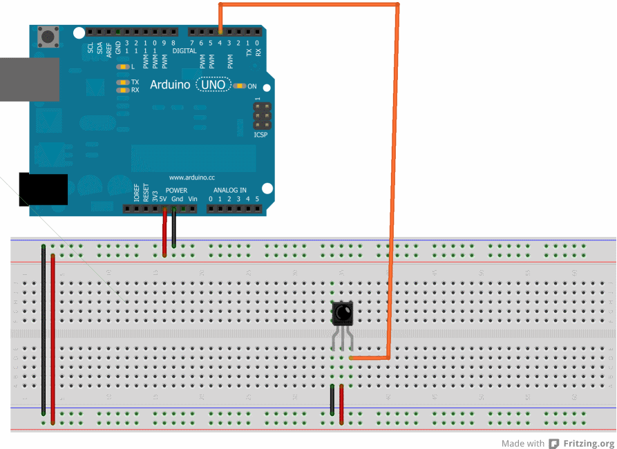
Connecting the receiver to the Arduino is really simple... There is only one pin to be connected to digital pin 4 (or any other pin if you decide to change the code), which is the data pin on the receiver. To power the receiver you also need to connect one or more pins to Ground and Vcc. Check the datasheet on the specific receiver you're using to find out which pins to connect.
The next image shows how to connect an infrared receiver as an example:
The following image shows my current configuration. I have both a radio and a infrared receiver in the same breadboard, then just connect the one I need to the Arduino.
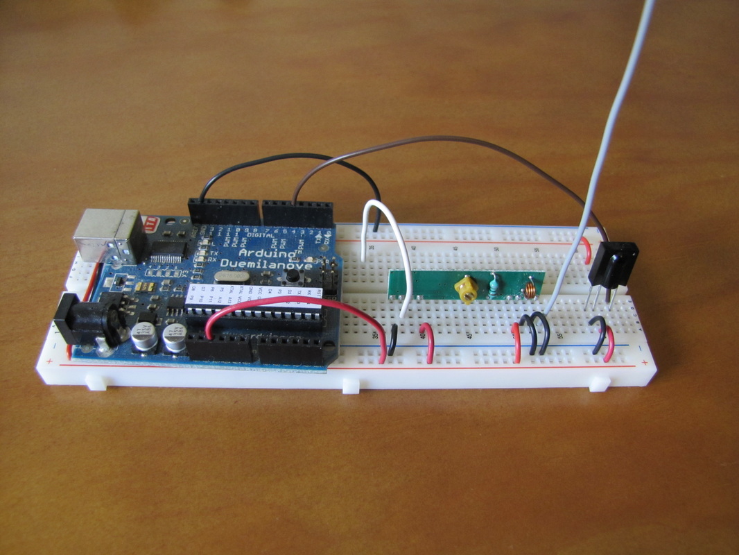
The brown and white wires are the data pins from the infrared and radio receivers. So I connect one of them to pin 4 on the arduino depending on the signal I want to read.
All it takes now is uploading the sketch SequenceReader to the Arduino and we're good to go. If your Arduino is an old one (with an Atmega 168 chip) it has less memory, so make sure you change the variable MAX_READINGS to 200 so it doesn't crash because of memory issues.
All it takes now is uploading the sketch SequenceReader to the Arduino and we're good to go. If your Arduino is an old one (with an Atmega 168 chip) it has less memory, so make sure you change the variable MAX_READINGS to 200 so it doesn't crash because of memory issues.
Getting started with SequenceDecoder
SequenceDecoder has only one window where all the information is presented. On startup it looks like this:
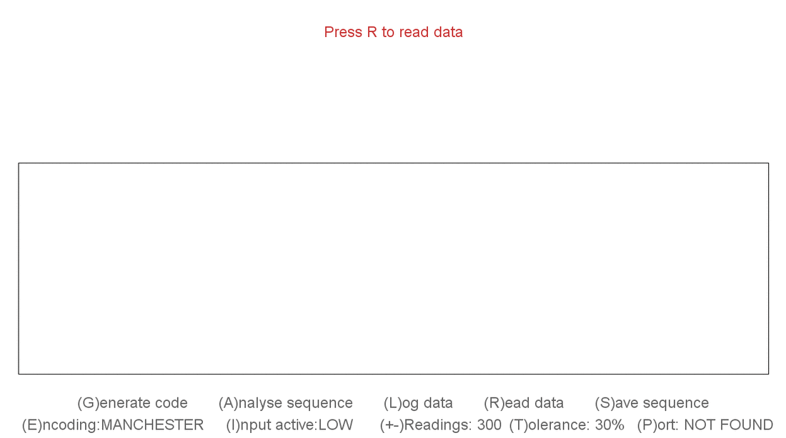
All of the options are listed on the bottom of the screen. Use or change them by clicking the keys between parenthesis.
The last line contains the parameters to set up the readings. For the variables on this line we can also use the left and right mouse buttons to increase or decrease the values:
The last line contains the parameters to set up the readings. For the variables on this line we can also use the left and right mouse buttons to increase or decrease the values:
- Encoding: chooses the encoding type. Supports pulse position and manchester based encodings. If you have no idea what this means, don't worry. The program tries to find out automatically what encoding is being used.
- Input Active: This depends on the type of receiver being used. For my experience, infrared receivers are usually active LOW, and radio receivers are usually active HIGH. This is not a rule though, check the documentation of your receiver to be sure. Or even simpler, try it both ways, the program will let you know if it things you have it the wrong way :P
- Readings: This is the number of different values read from the Arduino each time. ome codes can be read with only 20 values, others may take over 300... It all depends on how many bits are being transmitted. I would start with a high value and work it down.
- Tolerance: This is a percentage value used to assume if marks with different timings might be the same or not, since the pulses will not always have the same durations. For example, if we get a pulse of 1483 and one with 1535 microseconds, it's probable that they are both supposed to be a pulse of 1500 microseconds, so the program groups together pulses with similar durations. I find a 30% value seems to work fine in most cases.
- Port: Finally, the COM port... Simply select the one connected to the Arduino.
Reading and processing the sequences
When everything is set up, just press the R key to send the order for the Arduino to start reading values. The LED on pin 13 should light up when the order is received, and turn off again when all the values are read or a timeout occurs. Just press the R key and then any button on your remote for a couple seconds. If you get random readings even without pressing any button it may be because the receiver is picking up some noise (it's very common on radio signals). If this happens, you just need to start pressing the controller button before pressing the R key. This way the transmission will already have started and the arduino won't read any noise.
If things go well you should see something similar to the next picture:
If things go well you should see something similar to the next picture:
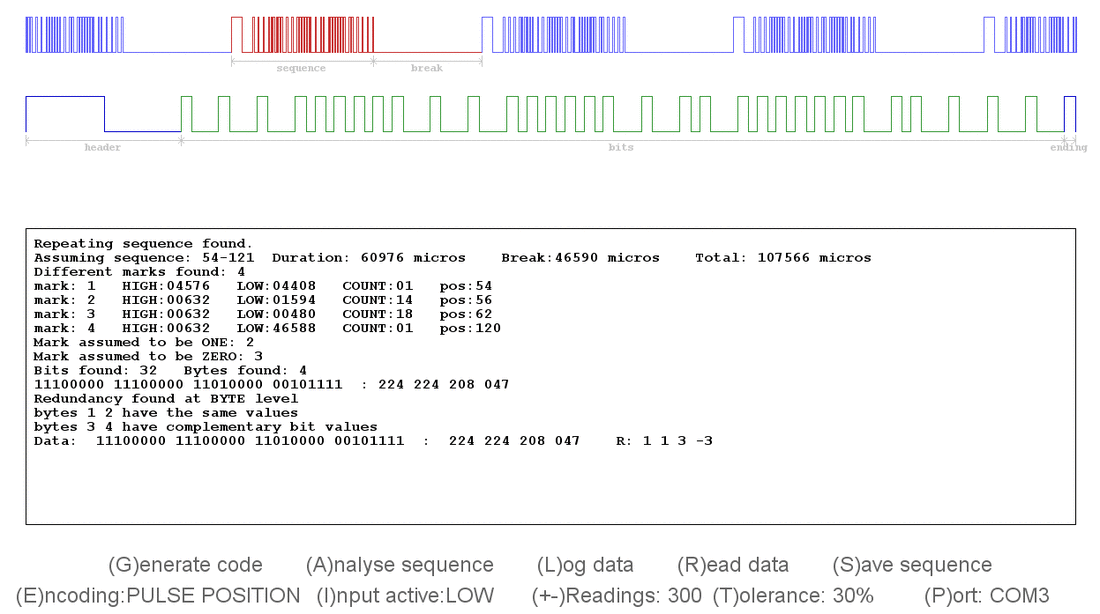
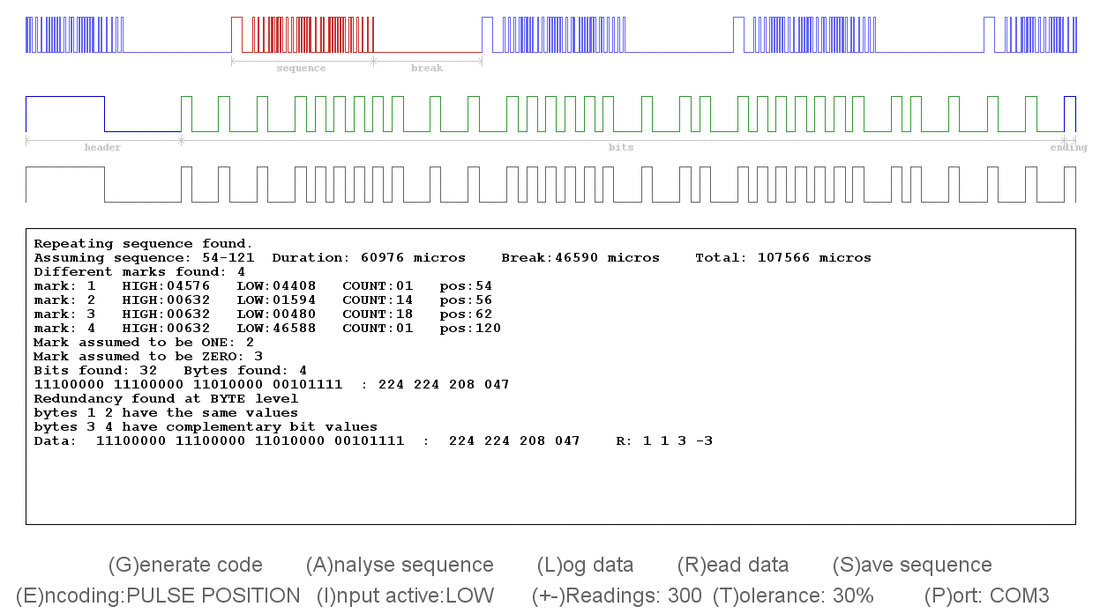
On the top is shown a graph showing all the values read from the Arduino. The program tries to find for a repeating pattern between breaks on that sequence. If a possible sequence was found, one of the iterations of that sequence is marked in red.
The second line is a "zoom" of the section in red, minus the break. This is where all the data should be. Analysing only this part, the program tries to find if there are specific marks in the beginning and/or end of the sequence, and assumes the bits are in the middle.
In the log is displayed some information that might be relevant to understand the sequences. It's not really necessary to understand how the sequences work in order to use them, the program creates all the code automatically. Pressing the G key automatically generates the Arduino code to send or receive codes matching these specifications. Something similar to this should appear on the log:
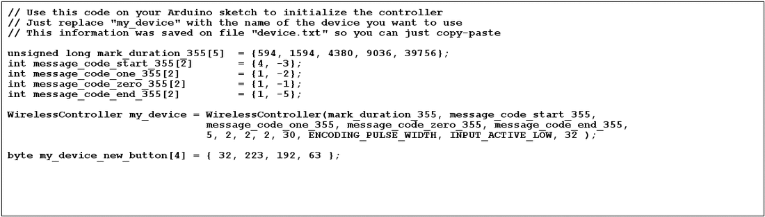
The easiest thing to do is open the file "device.txt" that should have been created in the same directory as the program. Just copy-paste the contents of that file to a new Arduino sketch and you're ready to start sending or receiving information. For more information on how to do this check the WirelessController page.
Advanced options
When for some reason the program does not find the sequence automatically, you can specify exactly where the sequence starts and ends. This often happen when the sequence is too big for the number of readings performed. By clicking the left and right mouse buttons over the first mark of the sequence(left) and the same mark when the sequence starts again(right). Clicking the key A will analyse this sequence again, same as it does when the information is read initially. The next screenshot shows an example of a sequence that was not found properly because there weren't enough readings to find a pattern:

We can see clearly that there is a repeating pattern here, but only one complete sequence was captured, so the program didn't assume the proper sequence. All you need to do is click to mark where the sequence starts and ends. In this example, you would left and right-click on the marked positions, and then just press A to analyse this new sequence.

The "Save sequence" option is used to save the current sequence in order to compare it to other readings in the future. Press the S key and the current sequence will appear as a third graph, and it will remain there until you save a new one, as shown on the next image:
Finally, the Log data option is an option to log all the codes read to a file called "log.txt". This option is useful when you are trying to find out what the bits in the message mean. Without knowing the protocol, the only way is to click several buttons, compare the values and try to infer some conclusions about it.
Understanding the information in the log
When processing a sequence, the program first displays some information about the sequence length and the duration of the different marks. This information should be easy to understand when looking at the values and the image at the same time.
After finding all the bits in the message, the program analyses the redundancy in the data. There can be redundancy at bit level or at byte level.
Redundancy at bit level means when we send a bit, we always send it more than once, or we send it once followed by the opposite bit. These kind of redundancies are processed automatically by the system and integrated in the piece of code generated automatically. Be aware that some specific messages may be mistaken by messages with redundancy. For instance, if the message we want to send has the bits: 00 11 00 11 00 11 00 11 the system will assume that each bit is sent twice, and that that the message can be simplified to: 01010101 There is a very low percentage of messages which can be mistaken by false redundancy, so the best way to be sure is to press a few different buttons . If the system detects the same pattern of redundancy in all of them, then we can assume it's correct. If it doesn't, make sure when you generate the code with the G key you are using a sequence without false redundancy.
Redundancy at byte level is similar to bit redundancy, but nothing is done upon it, so there isn't any problem if any false redundancy is found. Still, this information might be useful to simplify some code manually.
Let's analyse some button presses from a Samsung remote controller as an example:
Data: 11100000 11100000 00010110 11101001 : 224 224 022 233 R: 1 1 3 -3
Data: 11100000 11100000 00100000 11011111 : 224 224 032 223 R: 1 1 3 -3
Data: 11100000 11100000 10010000 01101111 : 224 224 144 111 R: 1 1 3 -3
Data: 11100000 11100000 00110000 11001111 : 224 224 048 207 R: 1 1 3 -3
Data: 11100000 11100000 11100000 00011111 : 224 224 224 031 R: 1 1 1 -1
Data: 11100000 11100000 11010000 00101111 : 224 224 208 047 R: 1 1 3 -3
Data: 11100000 11100000 11110010 00001101 : 224 224 242 013 R: 1 1 3 -3
Data: 11100000 11100000 10100110 01011001 : 224 224 166 089 R: 1 1 3 -3
As we can see in the redundancy information, almost every time we get the values ( 1 1 3 -3 )
This means the first and the second bytes are the same (from the 1 1) , and the fourth byte is the opposite of the third byte (from the 3 -3).There is one reading where we can see the values ( 1 1 1 -1 ) instead. This is exception, because when pressing this specific button the third byte has the same value as the two first ones. And since the fourth byte if the opposite of the third byte, it's also the opposite of the other ones. So the program says ( 1 1 1 -1 ), which means the first byte appears 3 times, and then the opposite appears 1 time. Still, it doesn't conflict with the ( 1 1 3 -3 ) rule.
So even though 4 bytes are always transmitted, there are actually only 2 bytes on relevant information. Also the first of those two relevant bytes never changes. This probably means that first byte is some kind of id for the controller, and the second byte refers to the button being pressed.
Using this information we can create simplifies versions of functions to send data to specific devices, instead of using the generic one from the library. For more information on how to use the library check the WirelessController page.
